
Regents Physics - Electric Current
Flow of Charge

Electric current is the flow of charge, much like water currents are the flow of water molecules. Water molecules tend to flow from areas of high gravitational potential energy to low gravitational potential energy. Electric currents flow from high electric potential to low electric potential. And the greater the difference between the high and low potential, the more current that flows!
In a majority of electric currents, the moving charges are negative electrons. However, due to historical reasons dating back to Ben Franklin, we say that conventional current flows in the direction positive charges would move. Although inconvenient, it's fairly easy to keep straight if you just remember that the actual moving charges, the electrons, flow in a direction opposite that of the electric current. With this in mind, we can state that positive current flows from high potential to low potential, even though the charge carriers (electrons) actually flow from low to high potential.
Electric current (I) is measured in amperes (A), or amps, and can be calculated by finding the total amount of charge (![]() q), in Coulombs, which passes a specific point in a given time (t). Electric current can therefore be calculated as:
q), in Coulombs, which passes a specific point in a given time (t). Electric current can therefore be calculated as:
Question: A charge of 30 Coulombs passes through a 24-ohm resistor in 6.0 seconds. What is the current through the resistor?
Answer:
Resistance
Electrical charges can move easily in some materials (conductors) and less freely in others (insulators), as we learned previously. We describe a material's ability to conduct electric charge as conductivity. Good conductors have high conductivities. The conductivity of a material depends on:
- Density of free charges available to move
- Mobility of those free charges
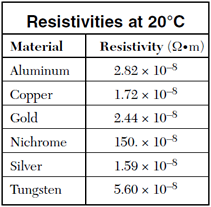
In similar fashion, we describe a material's ability to resist the movement of electric charge using resistivity, symbolized with the Greek letter rho (![]() ). Resistivity is measured in ohm-meters, which are represented by the Greek letter omega multiplied by meters (
). Resistivity is measured in ohm-meters, which are represented by the Greek letter omega multiplied by meters (![]() •m). Both conductivity and resistivity are properties of a material.
•m). Both conductivity and resistivity are properties of a material.

When an object is created out of a material, the material's tendency to conduct electricity, or conductance, depends on the material's conductivity as well as the material's shape. For example, a hollow cylindrical pipe has a higher conductivity of water than a cylindrical pipe filled with cotton. However, shape of the pipe also plays a role. A very thick but short pipe can conduct lots of water, yet a very narrow, very long pipe can't conduct as much water. Both geometry of the object and the object's composition influence its conductance.
Focusing on an object's ability to resist the flow of electrical charge, we find that objects made of high resistivity materials tend to impede electrical current flow and have a high resistance. Further, materials shaped into long, thin objects also increase an object's electrical resistance. Finally, objects typically exhibit higher resistivities at higher temperatures. We take all of these factors together to describe an object's resistance to the flow of electrical charge. Resistance is a functional property of an object that describes the object's ability to impede the flow of charge through it. Units of resistance are ohms (![]() ).
).
For any given temperature, we can calculate an object's electrical resistance, in ohms, using the following formula, which can be found on your reference table.
In this formula, R is the resistance of the object, in ohms (![]() ), rho (
), rho (![]() ) is
the resistivity of the material the object is made out of, in ohm*meters (
) is
the resistivity of the material the object is made out of, in ohm*meters (![]() •m), L is the length of the object, in meters, and A is the cross-sectional area of the object, in meters squared. Note that a table of material resistivities for a constant temperature is given to you on the reference table!
•m), L is the length of the object, in meters, and A is the cross-sectional area of the object, in meters squared. Note that a table of material resistivities for a constant temperature is given to you on the reference table!
Let's try a sample problem calculating the electrical resistance of an object:
Question: A 3.50-meter length of wire with a cross-sectional
area of 3.14×10⁻⁶ m2 at 20° Celsius has a resistance of 0.0625. Determine the resistivity of the wire and the material it is made out of.
Answer:
Ohm's Law
If resistance opposes current flow, and potential difference promotes current flow, it only makes sense that these quantities must somehow be related. George Ohm studied and quantified these relationships for conductors and resistors in a famous formula now known as Ohm's Law:
Ohm's Law may make more qualitative sense if we re-arrange it slightly:
Now it's easy to see that the current flowing through a conductor or resistor (in amps) is equal to the potential difference across the object (in volts) divided by the resistance of the object (in ohms). If you want a large current to flow, you would require a large potential difference (such as a large battery), and/or a very small resistance.
Question: The current in a wire is 24 amperes when connected to a 1.5 volt battery. Find the resistance of the wire.
Answer:
Note: Ohm's Law isn't truly a law of physics -- not all materials obey this relationship. It is, however, a very useful empirical relationship that accurately describes key electrical characteristics of conductors and resistors. One way to test if a material is ohmic (if it follows Ohm's Law) is to graph the voltage vs. current flow through the material. If the material obeys Ohm's Law, you'll get a linear relationship, and the slope of the line is equal to the material's resistance.

Electrical Circuits
An electrical circuit is a closed loop path through which current can flow. An electrical circuit can be made up of almost any materials (including humans if we're not careful!), but practically speaking, they are typically comprised of electrical devices such as wires, batteries, resistors, and switches. Conventional current will flow through a complete closed-loop path (closed circuit) from high potential to low potential, therefore electrons actually flow in the opposite direction, from low potential to high potential. If there the path isn't a closed loop (open circuit), no charge will flow.
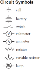
Electric circuits, which are three-dimensional constructs, are typically represented in two dimensions using diagrams known as circuit schematics. These schematics are simplified, standardized representations in which common circuit elements are represented with specific symbols, and wires connecting the elements in the circuit are represented by lines. Basic circuit schematic symbols are shown in the Physics Reference Table.
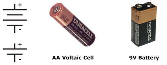
In order for current to flow through a circuit, you must have a source of potential difference. Typical sources of potential difference are voltaic cells, batteries (which are just two or more cells connected together), and power (voltage) supplies. We often times refer to voltaic cells as batteries in common terminology. In drawing a cell or battery on a circuit schematic, remember that the longer side of the symbol is the positive terminal.
Electric circuits must form a complete conducting path in order for current to flow. In the example circuit shown below left, the circuit is incomplete because the switch is open, therefore no current will flow and the lamp will not light. In the circuit below right, however, the switch is closed, creating a closed loop path. Current will flow and the lamp will light up.
Note that in the picture at right, conventional current will flow from positive to negative, creating a clockwise current path in the circuit. The actual electrons in the wire, however, are flowing in the opposite direction, or counter-clockwise.
Voltmeters
Voltmeters are tools used to measure the potential difference between two points in a circuit. The voltmeter is connected in parallel with the element to be measured, meaning an alternate current path around the element to be measured and through the voltmeter is created. You have connected a voltmeter correctly if you can remove the voltmeter from the circuit without breaking the circuit. In the diagram at right, a voltmeter is connected to correctly measure the potential difference across the lamp. Voltmeters have very high resistance so as to minimize the current flow through the voltmeter and the voltmeter's impact on the circuit.
Ammeters
Ammeters are tools used to measure the current in a circuit. The ammeter is connected in series with the circuit, so that the current to be measured flows directly through the ammeter. The circuit must be broken to correctly insert an ammeter. Ammeters have very low resistance to minimize the potential drop through the ammeter and the ammeter's impact on the circuit, so inserting an ammeter into a circuit in parallel can result in extremely high currents and may destroy the ammeter. In the diagram at right, an ammeter is connected correctly to measure the current flowing through the circuit.
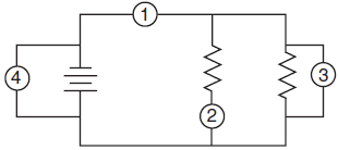
Question: In the electric circuit diagram at right, possible locations of an ammeter and a voltmeter are indicated by circles 1, 2, 3, and 4. Where should an ammeter be located to correctly measure the total current and where should a voltmeter be located to correctly measure the total voltage?
Answer: To measure the total current, the ammeter must be placed at position 1, as all the current in the circuit must pass through this wire, and ammeters are always connected in series.
To measure the total voltage in the circuit, the voltmeter could be placed at either position 3 or position 4. Voltmeters are always placed in parallel with the circuit element being analyzed, and positions 3 and 4 are equivalent because they are connected with wires (and potential is always the same anywhere in an ideal wire).
Energy & Power
Just like mechanical power is the rate at which mechanical energy is expended, electrical power is the rate at which electrical energy is expended. We learned previously that when you do work on something you change its energy, and that electrical work or energy is equal to charge times potential difference. Therefore, we can write our equation for electrical power as:
We also know, however, that the amount of charge moving past a point per given unit of time is current, therefore we can continue our derivation as follows:
So electrical power expended in a circuit is the electrical current multiplied by potential difference (voltage). Using Ohm's Law, we can expand this even further to provide us with several different methods for calculating electrical power dissipated by a resistor:
Of course, conservation of energy still applies, so the energy used in the resistor is converted into heat (in most cases) and light, or it can be used to do work. Let's see if we can't put this knowledge to use in a practical application.
Question: A 110-volt toaster oven draws a current of 6 amps on its highest setting as it converted electrical energy into thermal energy. What is the toaster's maximum power rating?
Answer: